Post 6 from my old blog - building hand made turnouts:
As mentioned in my last post, I have discovered that a Dremel type moto-tool makes an excellent point shaping tool for constructing model railroad turnouts. Combined with the simple jig below I found the process to be much easier and faster than the traditional filing method.
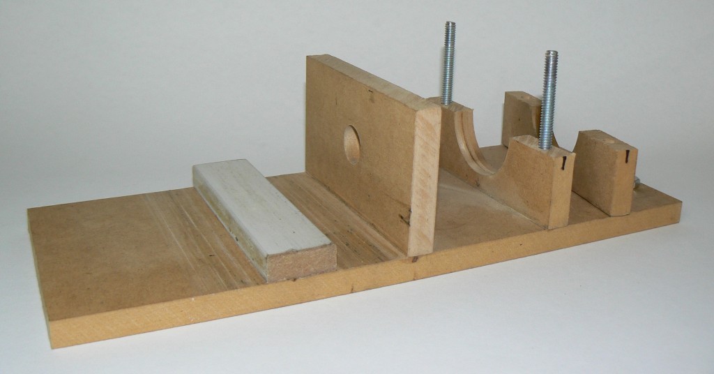
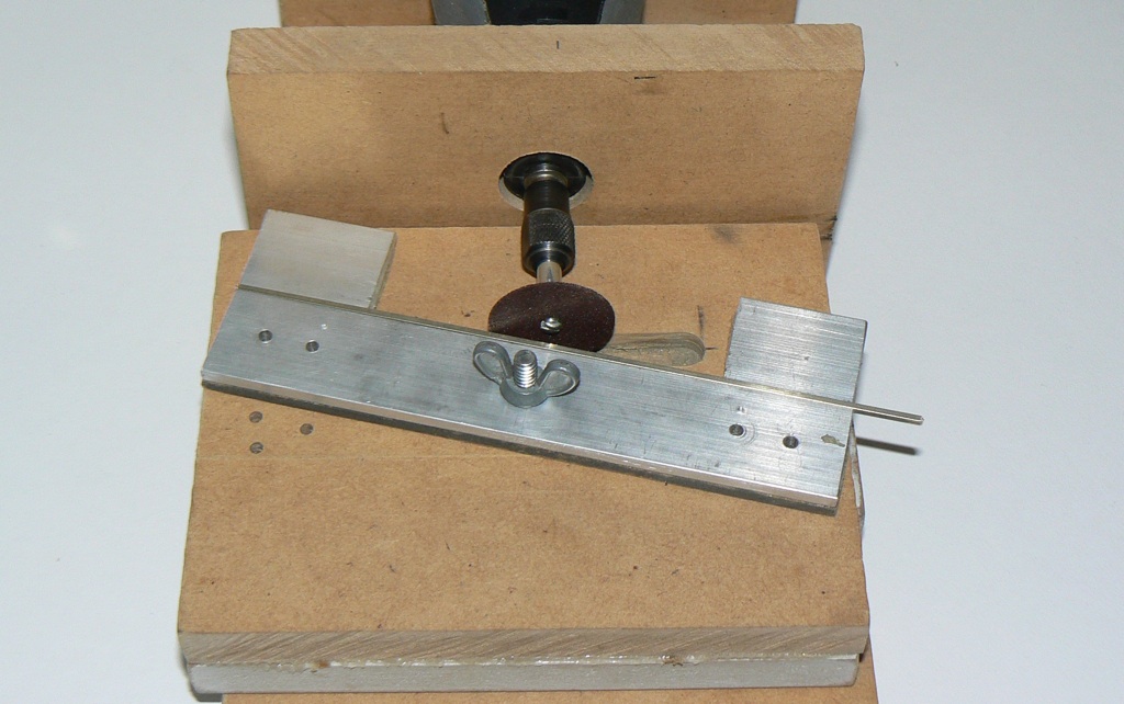
Here is a picture of the completed unit:

The idea is that rail is placed upside down between 2 aluminium strips that secure it tightly. This holder is then mounted on a slide that moves past the Dremel tool. The holder can swivel to create different angles. I use No. 409 cut off disks to cut and shape the rails. Points, stock rail notches and frogs can all be made with this jig.
While a bit fiddley, this arrangement allows angles of 1:25 or less to be ground fairly easily and accurately.
The moto-tool holding part of the jig:
The details of this part will vary depending on the moto tool used, but I used a 300mm x 120mm piece of 12mm mdf for the base and two up-right pieces to hold the tool. A 19mm hole cut in the front piece gave me a good fit for a 300 series Dremel tool. This was drilled with a spade bit. The rear upright has a 50mm hole which is a bit large. I cut this with a hole saw. This piece was then cut in half and bolts passed through it from the base. The bolt heads were recessed into the base so that the jig sits flat. A piece of rubber was glued to the upper hole to provide a snug fit for the tool when the nuts are tightened. Calculations for the heights of these two holes above the baseboard are described below. Standard glued butt joints were used.
The slider part of the jig:
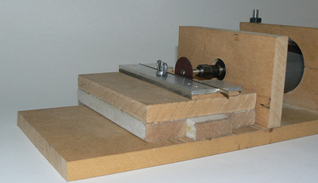
This consists of a base of 12mm mdf with 2 runners underneath that slide along the fixed piece of mdf attached to the base. These are made from 12mm x 30mm mdf. When the runners are glued to the base they are also clamped on their side tightly against a third piece acting as the slider. A shim made of a piece of paper is added to provide a small bit of clearance. After the glue has dried the slide edges that contact each other are rubbed with candle wax to allow smooth running. The top of slider base has a wide groove across it to provide clearance for the cutoff bit. This was cut with a router. On top of the base is a swiveling jig made of three strips of 3mm thick aluminum glued to a thin 3mm mdf base. These aluminium strips hold the rail tightly upside down against the cutoff tool.
The rail holder:
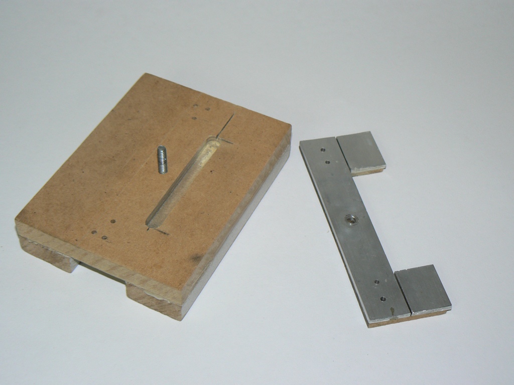
After the strips of aluminium have been glued to the 3mm base, the base mdf is cut out to form a ‘C’ shaped holder. I used contact cement to glue the first aluminium strip to one edge of the base and after it dried added the two shorter piece on the other side. A section of rail was used to keep the right gap between the strips. To remove the inner part of the ‘C’, just cut down each side at the top and bottom of the ‘C’ with a small saw and use a scoring knife to score the base along the long side of the ‘C’, next to the long aluminium strip. Score each side several times, then bend the piece back and forward until it comes apart.
This rail holder is attached to the slider base using a small bolt at its center, so that it can swivel. The bolt is recessed into the base of the slider. When the holder is parallel to the cutoff bit there is a gap of about 4 mm to allow for the rail and adjustment of the cutoff bit.
Position of Dremel Tool holes - The height of the rail holder in relation to the cutoff wheel is important. The height needs to be such that the rail top (actually the bottom as it is upside down) is just a few mm below the center of the cutoff wheel. The gives allowance for the bolt holding the cutoff wheel. The actual height needs to be calculated according to the materials used to construct the slider part of the jig, which is then used to figure out the locations of the two holes holding the moto-tool.
Grinding and cutting
Don’t forget safety precautions - glasses etc. To make a turnout you need to cut or grind 6 pieces of rail:
- Two pieces for the stock rails just have a small section ground away.
- Two other pieces for the point rails are ground to a sharp point at about 1:25 angle or less.
- The last two pieces make up the frog. These are cut at the frog angle, and one piece needs a further area removed so the other rail butts up properly.
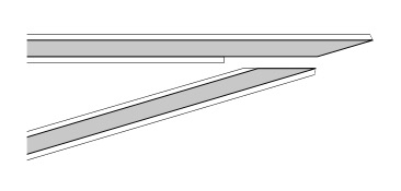
I have a couple of holes drilled through the rail holder to consistently get the same angle. I use a carpenters angle to set a new angle and then drill a hole through the rail holder and into the base. Then when I need to reproduce the angle I insert a drill bit into the correct hole after the hole is aligned with the corresponding hole in the base. Each new angle actually requires that the rail holder be set to the same but opposite angle as well. A bit hard to explain so here is a diagram:

For a number 6 turnout I am using 1:25 for both the points and the corresponding groove in the stock rails and of course 1:6 for the frog.
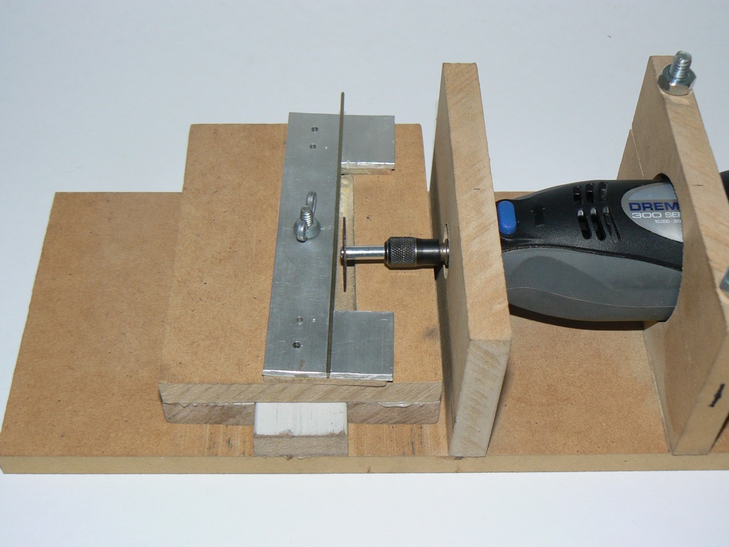
To cut, just add a piece of rail - base side up - to the holder and adjust the cutoff wheel so it starts the cut where you want it. Using a medium tool speed gently move the slider across and make the cut. When cutting a point I cut until just before it breaks through the rail and then clip off the last piece by hand. This prevents the ground point from sometimes being dragged down between the holder and the cutoff wheel.
Grinding the stock rails is similar except you only cut the groove a short distance - less than half way though the rail. It takes a bit of practice to get the cut to start and end where you want it, and also how far through to cut the stock rail, but once you figure out where to make the cuts, it is quite reproducible:

It also gets a bit confusing working out which way to do the cut, as the rail is upside down, but basically you want to cut a point and stock rail in one direction, then adjust the jig to the opposite but same angle and cut another point and stock rail. A point and stock rail from each direction then make a pair.
The 2 frog rails are cut from two different directions as well. A small section of one of the rails also has part of the wider base ground flush with the side of the rail:
Notes:
- The cutoff wheels wear out after a smallish number of cuts - about 3 turnouts worth - and need to be replaced at the first sign of wear. I’ve used generic cutoff wheels without problems and they are quite cheap.
- When cutting a stock and point rail pair with the angle pointing away from the rail you have to ‘back into’ the rail to cut it. The rail will tend to lift out of the jig in this case so you have to hold it a bit more firmly.
- I may try cutting the stock rail notch at a smaller angle than the point. Perhaps 1:30
- The point angle - 1:25 may need to be modified for different frog angles. I have only made No. 6 turnouts so far and 1:25 looks about right.
- If I was building the jig again I would consider making the rail holder ‘C’ part from thicker mdf. If it was say 12mm and the cutoff wheels were small you wouldn’t need to router a clearance slot in the slider base and adjusting the cutoff wheel would be easier.
After the rails are ground I clean them up with a file and sometimes an oilstone. None of the jig dimensions are that critical but you may have to experiment a bit to get it right.